OMEGA
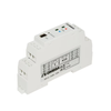
TXDIN1600S DIN Rail Strain Gage/ Load Cell Transmitter w/Bipolar mA/V Output
Smart Powered Strain Bridge/Load Cell Conditioner
The TXDIN1600S is a “smart” powered bridge amplifier for use with strain gauges or load cell signals. The product has a built-in capability to scale the input signal to a process value while the output stage offers either voltage, bipolar voltage or active/passive current re-transmission signals.
The TXDIN1600S requires an AC/DC power supply that will operate in the range (10 to 48) Vdc and 10 to 32 Vac making the device ideal for battery operation. An additional volt free contact input is available for tare setting using a remote switch. The high precision input stage of the device allows for a bridge excitation voltage of 5 Vdc to be used as opposed to the traditional 10 Vdc. This reduces the power requirement for the bridge supply and up to four bridges (cells) may be connected to the input.
The device is provided with two front panel push buttons that can be configured to perform one of two functions or be disabled. Set as function 1, the buttons allow the user to push button configure the output range at high and low scale against a live input signal, set as function 2, the buttons allow the operator to trim the output at high and low scale. The device uses ratio metric measurement to obtain high stability.
The product uses a USB port for configuration, together with a simple to use menu driven software configuration tool, allowing the user to take advantage of the product’s comprehensive specification. Additionally, the user may read live process data when connected to the PC, allowing for offset and span calibration.
If configuration is not specified at the time of order, the product will be shipped with the default range 2 mV/V input, 4 to 20 mA output.
• Suitable for Load Cell/Strain Gauge Applications
• Universal Current, Bipolar Voltage Outputs
• Input Range 0.2 to 7.5 MV/V, 5 V Excitation
• Powered 10 to 32 Vac or 10 to 48 Vdc Supply
Request a Calibration Quote
We’re here to make calibration easy. Request a quote today and let our team give you the care, precision, and service you can trust.
Learn moreBrowse By Brands
Uncover the brands that set the standard for quality and dependability in every industry we serve.
Learn more