OMEGA
DRSL-LPI-2 DIN Rail Input loop Powered Isolators w/ 1 or 2 Channels
DIN Rail Input Loop-Powered Isolators
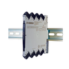
The DRSL-LPI Series DIN rail input loop powered isolators provide a competitive choice in terms of both price and technology for galvanic isolation of current signals to SCADA systems or PLC equipment. These units provide isolation and 1:1 conversion of standard current signals and are powered by the analog input current signal loop.
The DRSL-LPI series offers isolation between input and output, provides surge suppression and protects control systems from transients and noise. These units also eliminate ground loops and can be used for measuring floating signals. Low power consumption facilitates DIN rail mounting without the need for any air gap. Measurement ranges are factory calibrated. These isolators operates over a wide temperature range from -25 to 70°C (-13 to 158°F).
• 1 Channel (DRSL-LPI-1) or 2 Channel (DRSL-LPI-2) Input Loop Powered Isolators
• Powered by the Analog Input Current Signal Loop
• 1:1 Signal Ratio
• Low Input Voltage Drop
 OMEGA
OMEGADRSL-MOD-STOP
Module stop (screwed onto DIN rail to support and hold mounted devices)
Call Today!
800-567-8686Normally ships in 2-3 weeks![RA Il 35 1 12980]() OMEGA
OMEGARAIl-35-1
35 mm DIN rail, 1 m (3.3') length
Call Today!
800-567-8686Normally ships in 2-3 weeks

Request a Calibration Quote
We’re here to make calibration easy. Request a quote today and let our team give you the care, precision, and service you can trust.
Learn moreBrowse By Brands
Uncover the brands that set the standard for quality and dependability in every industry we serve.
Learn more